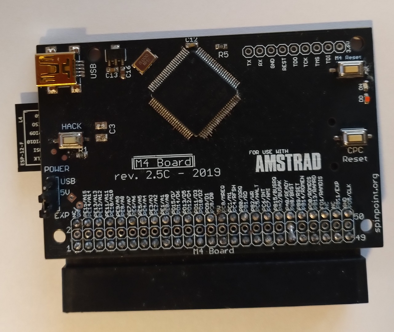
After nearly 10 years and close to 1500 pcs, I have decided to stop producing the M4 board. Finding time and motivation for builds has become increasingly challenging, and more EU bureaucracy starting October 1st was the final nail in the coffin.
Demand for the M4 board remains high, and I’m sorry to all those requests I haven’t replied to recently — I was waiting to make this announcement.
My apologies also to those on the waiting list, I won’t be able to build.
If anyone wants to build them or make their own, you are welcome to do so.
The heartfelt feedback from so many positive people has made the countless hours spent placing 0603 caps and resistors and removing solder bridges, less painful. 🙂
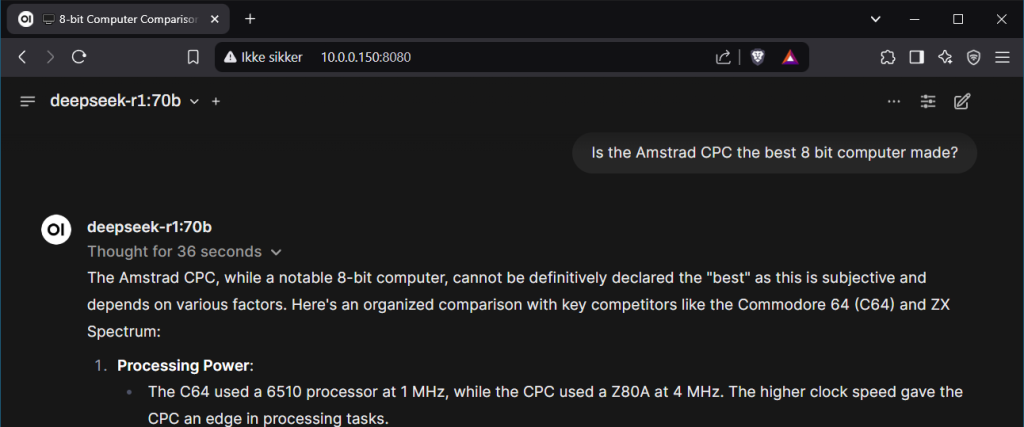
A few weeks ago, I read about the release of DeepSeek-R1 . An apparently open-source model that can run on relatively affordable hardware in distilled versions. This immediately caught my interest. I wanted to run AI models on my own hardware (being oldskool and all) and learn about training, fine-tuning, inference, and development.
Choosing the hardware
The first step was building a machine that I could afford while ensuring it could run decent distilled models. My choice : 2 (yes two!) NVIDIA RTX 3090 GPUs, each featuring 24GB of VRAM, connected via NVLink at a high-speed bandwidth of 56.248 GB/s (4×14.062), effectively providing 48GB of VRAM. This setup would allow me to run models like DeepSeek-R1-Distill-Llama-70B.
However, the process turned out to be more complicated than I expected.
Problems
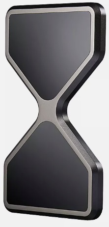
The NVLink bridge required for RTX 3090 cards is rare and expensive. The NVLink (former SLI) bridges used for RTX Titan, RTX 2000 series etc. are not compatible. Slot Spacing Issues: The official NVIDIA NVLink bridge for the RTX 3090 is a four-slot bridge, meaning there must be two empty slots between the PCIe 4.0 slots used for the GPUs.
NVLink
Motherboard However, finding a modern consumer motherboard with this spacing is difficult, if not impossible. You can link RTX 3090 cards of different brands, but the NVLink connectors are not always in the same position. You can use NVLink for RTX A6000, which is available in 3-slots, however you need 2 cards with NVLink connector at same position and one card should be less or equal to 2 slots and you will have heating issues. It could perhaps be solved using water cooling for atleast one card, to give it a low enough profile and enough cooling.
Solution
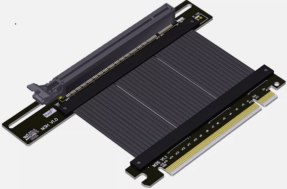
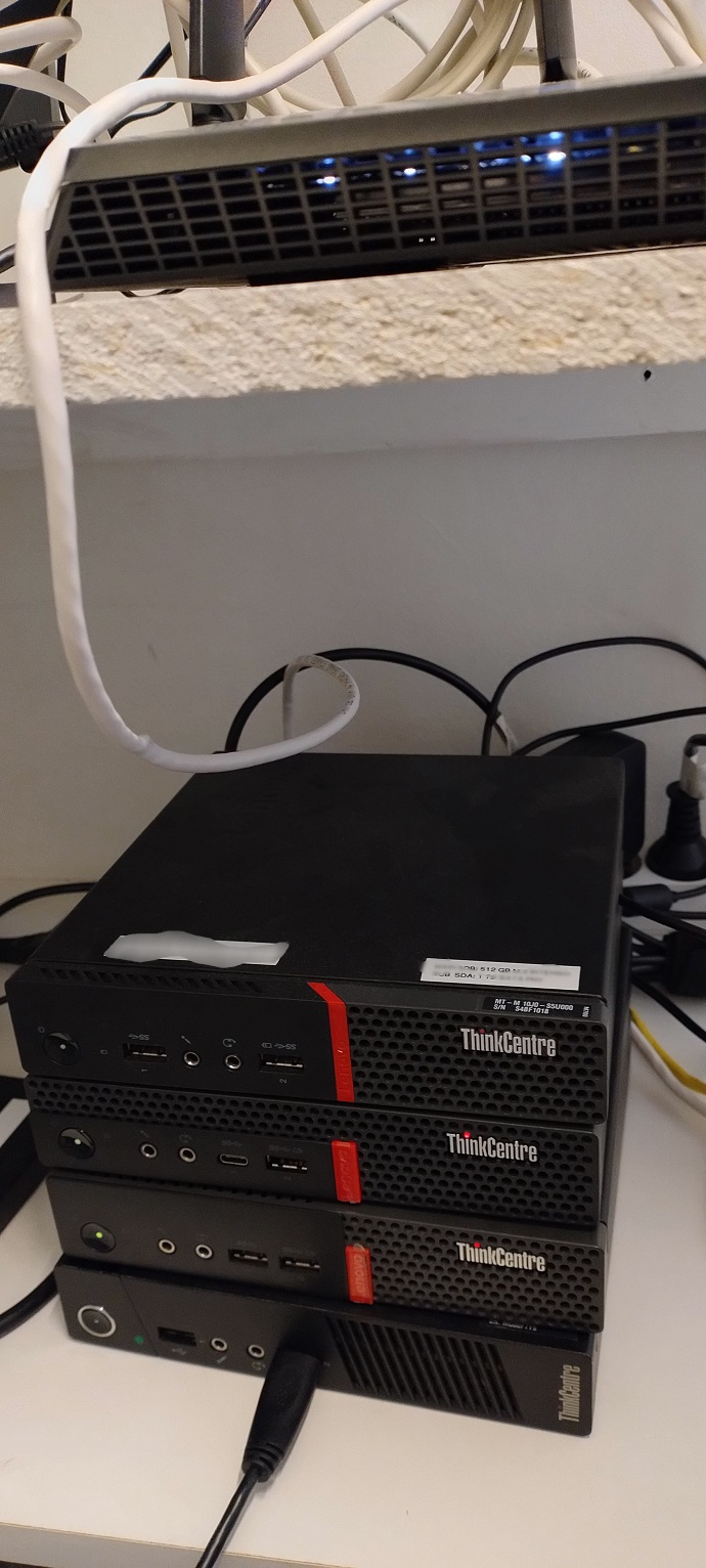
I opted for a case large enough to simulate a 2 slot spacing with good airflow I used a PCIe 4.0 riser cable to adjust the spacing and allow for correct placement to fit the NVLink. To accommodate the riser cable, I combined a card with a wider PCB (Founders Edition) with one that had a narrower PCB (ZOTAC Trinity OC), ensuring enough room for placement.
Installed the RTX 3090 FE in the top PCIe 4.0 slot.
Used the riser cable to bend 180 degrees from the second PCIe 4.0 slot, allowing the connector to lie flat over the motherboard’s cooling profiles, creating the necessary two-slot spacing. Addressed the difference in NVLink connector positions (31mm on the ZOTAC vs. 17mm on the FE) by leveraging the riser cable’s flexibility. Used an empty PCI slot bracket with standoffs to create the correct offset in both height and alignment. (The fat blue wire in the picture to the right, is to hold the bend riser cable away from the fan of the 3090 FE).
Riser Cable & spacing.
Riser Cable
back side
Software
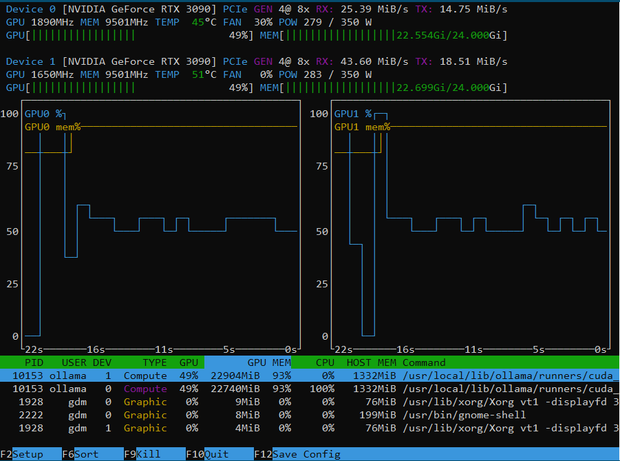
Once the hardware was in place, I installed Ubuntu 24.04.2 LTS, set up Ollama with various AI models, Open WebUI and SSH, so I could do everything remotely. (Fine tuning needed?!)
Running
The airflow in the case is excellent, which is why I prefer to keep the setup away from my workspace (sounds a bit like a low noise air conditioner). The maximum temperature reached so far when running DeepSeek-R1:70B is 73°C.
Running smoothly.
Final thoughts
This write up is primarily meant to help others who want to build a similar system. Information on this topic is scarce and scattered across the net.
Even though I bought my RTX 3090s second-hand, they are still very expensive. However, they remain one of the best options for running AI models at home due to their 24GB VRAM and Tensor & CUDA cores. I might share further updates as I progress—there’s much to learn! Maybe there will be a model/dataset with dedicated retro computer programming data – who knows 🙂
During the last few days, my server provider had a server failure. After some effort I was able to put the site back up, now running on my own servers. I think the website is now fully functional again, but the mail server is still not 100% OK, so please have some patience, if you have emailed me. I will put an update here once I am sure mail server is fully functional, and I will have to ask you to resend any mails within the last week. My apologies. And no worries, I am still building the M4’s, just behind schedule as always…
/Duke, 17th of March 2024
Update, 18th of March 2024: Incoming mail server seems to be fully OK now. Please re-send any emails send during the last week. My outgoing mail server still needs some work not to be seen as a spammer, so please check you junk/spam folders, when expecting a reply from me. Thanks for your patience. Update, 10th of September 2024: Changing ISP. DNS delegation taking place, hopefully all good by tomorrow.
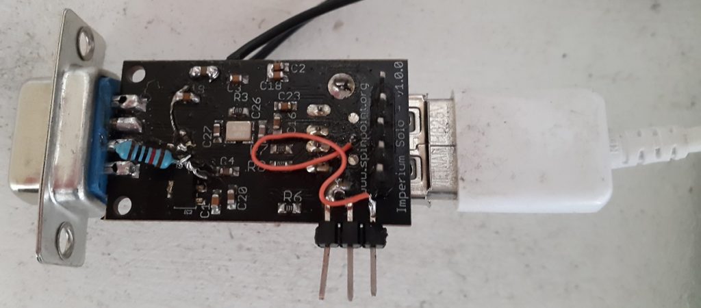
A new firmware for the Imperium Solo USB now adds support for the AGA Amiga console, CD32. All original controller buttons are supported (granted your USB controller has enough) – See the CD32 mappings in the Imperium Solo Database .
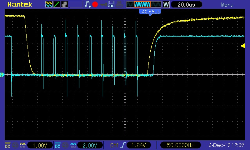
The CD32 was a little tricky, like the SEGA MD/Genesis as it has more buttons than wires. So it switches between regular joystick mode and an “Assert , CLK, serial stream”-scheme to give information about the extended buttons.
Here is what it looks like on the scope:
Lastly a short video showing it in use:
Notice that I made a seperate site for Imperium Solo, here:
Where you can see the database of tested Game controllers and mice, along with their button mapping.
Imperium Solo USB is an adapter to support modern day USB game controllers (&mice) on retro hardware. Today I am happy to announce that I added support for the great SEGA MegaDrive/Genesis console. It was not all trivial, due to the SEGA 6 button mode, which is now fully supported by Imperium Solo USB, granted you have enough buttons on your controller, check the database at the Imperium Solo infosite.
Furthermore SEGA choose to use VCC on another pin than the “atari-standard”, thus existing Imperium Solo PCB’s are not able to support it. However it was added as configuration option in PCB rev. 1.0.4. External power can also be applied via a USB micro socket (standard mobile phone charger would work), if extra power is needed. Options are configurable via jumpers.
Here’s a short video demonstration:
Notice that I made a seperate site for Imperium Solo, here:
Where you can see the database of tested Game controllers and mice, along with their button mapping.
Finally got around to writing the firmware changes needed to support Amiga and Atari ST via the Imperium Solo USB adapter.
Here’s a video of Amiga version:
Atari ST video:
When I release the firmware updates, you can re-program the existing Imperium Solo C64 hardware with them, but not the Imperium Solo Amstrad CPC, as there is jumper settings via 0 ohm smd resisters that needs to be changed to be used on other hardware than the Amstrad CPC.
Notice that I made a seperate site for Imperium Solo, here:
Where you can see the database of tested Game controllers and mice, along with their button mapping.
Small update on the Imperium Solo project initially released for the Amstrad CPC. Made some changes to the firmware and changed two 0 ohm SMD resistor settings to support Commodore 64 and probably many other retro computers with my modern USB controllers to joystick adapter.
For now I used an external 5V powersupply, as you can only draw a limited amount of current over the C64 joystick port* and power usage will depend on the controllers plugged into the adapter (the adapter itself uses very little). Will see first if there is interest at all for this adapter (maybe something similar already exist?). Anyway here is a video of the C64 prelimary version.
*It turns out the 100mA limit per Joystick port (200mA total), is a limit of what the stock powersupply can deliver safely while keeping the system stable. Otherwise the 5V on the joystick port is directly connected to the PSU input with a nice fat trace. So if using a better powersupply or the devices connected to the joystick port use less than 200 mA current, there is no need for external powersupply.
About mouse support. It is just joystick mode (1350). I cannot support the analog mouse mode (1351) with current PCB layout atleast.
Imperium Solo is a USB to joystick adapter, intended for using USB gamepads, like DualShock 3/4, XBOX One controller on retro computers. It’s also possible to use USB mouse. For now the project only supports the Amstrad CPC range of computers, but I plan to make firmware updates for use with other retro computers.
The firmware is updatable by pluggin in an USB stick/drive (FAT32) with the correct file when the adapter is powered on.
Special supported controllers are only DualShock 3, DualShock 4, XBox One controller and SNES USB controller. Other USB HID controllers should work by using my generic HID parser, but controller mapping may not be ideal for those. So I hope to add more controllers with the help of feedback from users.
USB Mouse is also using my generic HID parser, which atleast works with the 5 different USB mice I had laying around. At a point I made a custom mouse mode, with 5 bit resolution for delta values making it possible to get much better mouse feeling(proportional mode). This may be implemented to a later firmware update, if there is demand (it will need adapted software to be usable).
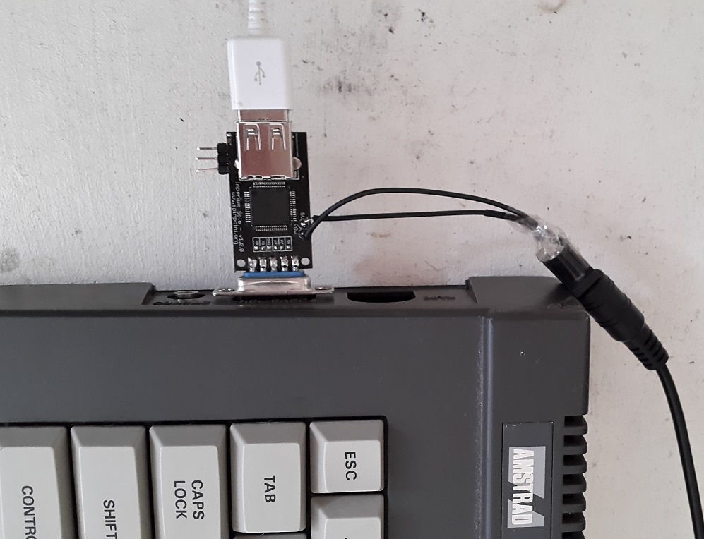
Made as compact as possible!
Below you can see a video of :
Installation/Connecting (notice most other retro computeres have power on the joystick port, so will not need DC splitter cable like the Amstrad is using)
Playing a game with USB controller
Playing a game with USB mouse
Playing a game with TWO usb controllers
Will update later with documentation (controller mapping, firmware upgrade etc).
Lastly expect another update, when I add firmware for the next retro computer.
The M4 board for the Amstrad CPC computer series has now surpassed more than 600 shipped units. And I expect to pass 700 units this year, if things continue as now.
Though there hasn’t been any recent updates on this blog for the M4 board, I have released some firmware updates adding new features.
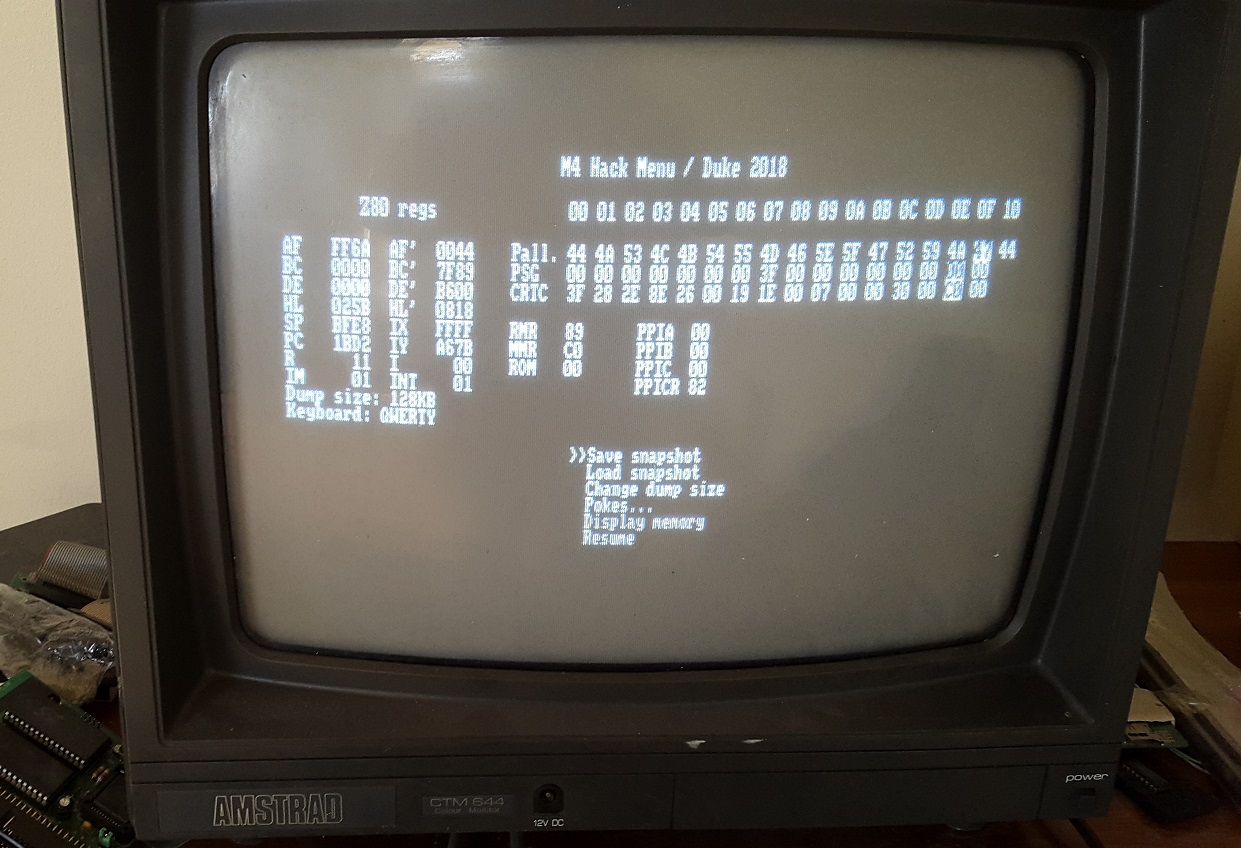
The biggest update came last year, when I added Hack Menu which is NMI triggering with ROM/RAM remapping. Making it possible to have “Multiface 2” like features.
For existing users it can be launched via the web-interface or by manually soldering a switch onto the board.
As can be seen on the video above, it is now possible to save game progress and re-load it again, using the popular .SNA format, which is compatible with many emulators aswell.
However it is still in beta so it can crash under some circumstances. I expect to do some major software improvement to this Hack menu.
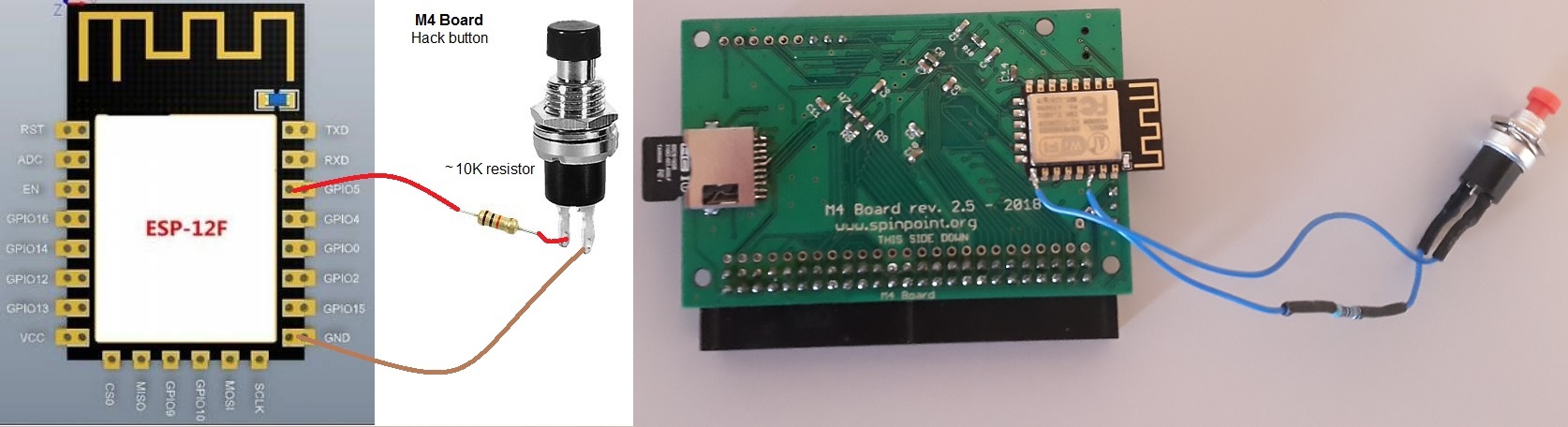
How to add the Hack button to existing PCB’s.
Adding Hack menu button
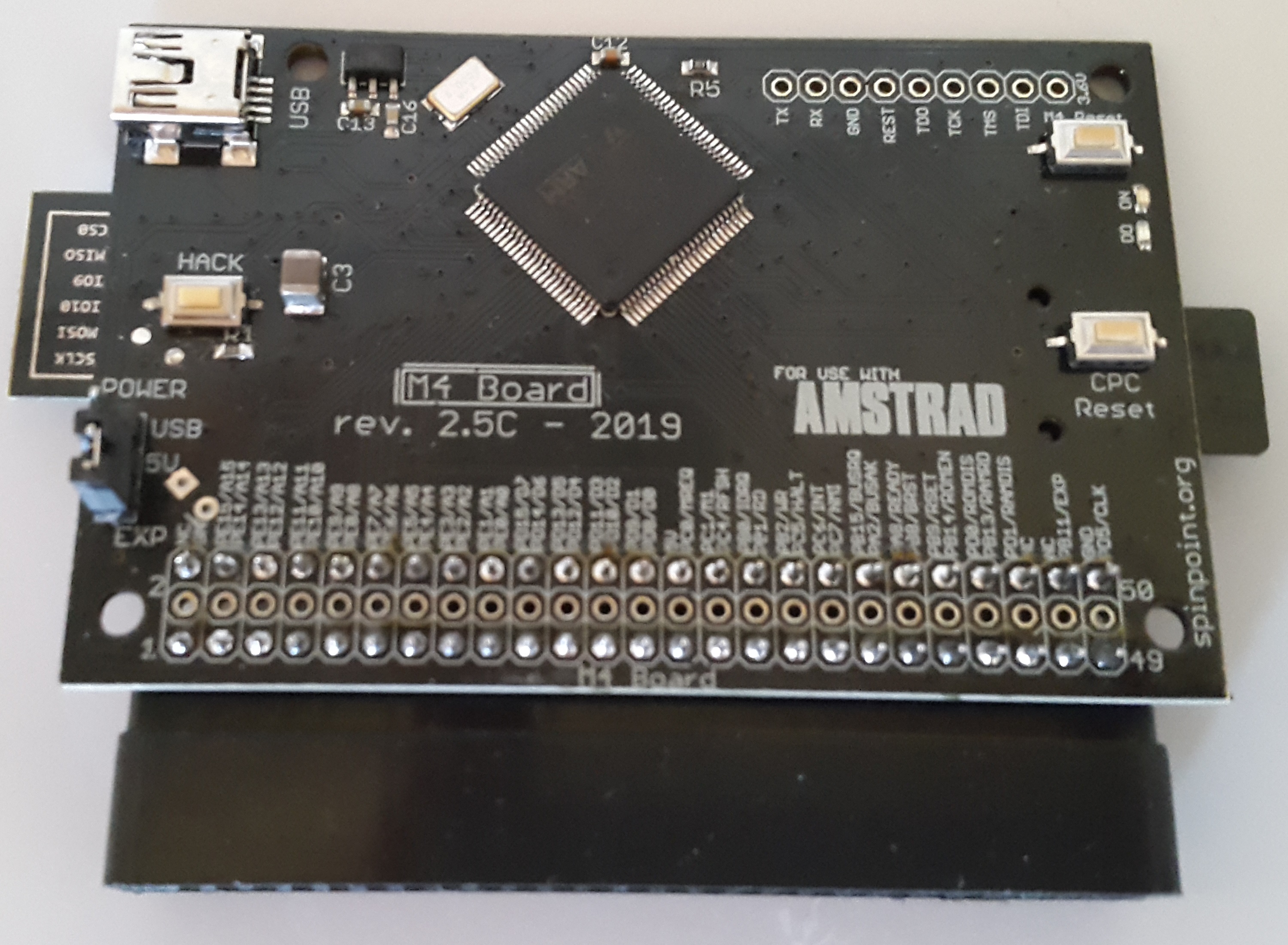
Meanwhile I updated the PCB once again to have this new Hack button.
Hack menu button added to PCB (left – middle)
The PCB now being version 2.5C.
M7 Board
So what about M7 / Galaxy Board / Zen80 board ? It’s not cancelled, but I haven’t really worked on it for a long while, I do have some overall changes in mind and hope to pick it up again.
Imperium Solo
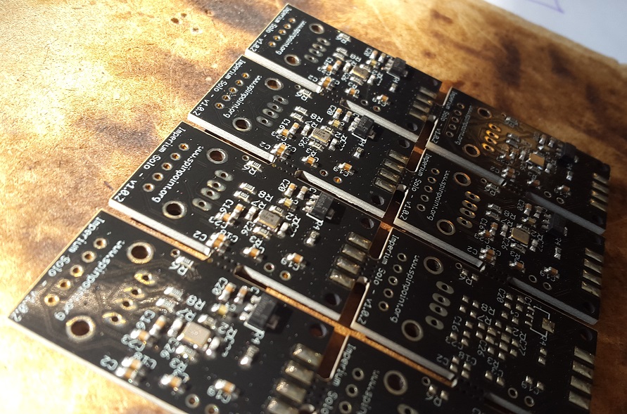
Beta PCB hacks!
Imperium Solo – USB joypads
I also made a USB to joystick adapter called Imperium Solo, which is also partial functionality of the Galaxy board. Its intended use is to be able to connect USB joypads and mouses to the joystick port. For now it supports CPC, but later it’s meant to be working with ZX Spectrum +2/+3, C64, Atari ST and Amiga. Or well lets wait and see 😉
Video showing the use of Dualshock 3/4 controllers on an Amstrad CPC!
I will update more on this soon, as I am awaiting the final PCB.